KOBOLD Pitot Tube-Differential Pressure ANU
Pitot tube sensors are classified as differential pressure sensors for flow measurement.
Connection: G1 … G 1½, 1 … 1½” NPT, DN25 … 80, ANSI 1 … 3″.
Material: stainless steel.
pmax: 400 bar.
tmax: 1175 °C.
Probe length: 50 … 8000 mm (2″ … 600″).
Description
Pitot Tube-Differential Pressure ANU
Pitot tube sensors are designated as flow measurement Differential Pressure Sensors.
The differences between the dynamic pressure on the upstream side and the static pressure on the downstream side are used in the measuring principle of a pitot tube. Pitot tube sensors are used to detect the flow of gases, liquids, and steam. Pitot tube sensors have a lower pressure loss than primary devices that measure flow via differential pressure. The pitot tube sensors can be produced in a variety of materials, such as Alloy c 276, Alloy 625, Alloy 400, 600, 800 PTFE, PVDF, etc., depending on the working pressure and temperature. temperature sensor s an optional Component of the pitot tube sensor (RTD or TC).
Applications:-
- Power generation.
- Oil production and refining.
- Water treatment and distribution.
- Gas processing and transmission.
- Chemical and petrochemical industry.
Technical Specifications Limitations:-
Exceeding the KOBAR Pitot Tube technical specifications limitations printed on the KOBAR Pitot Tube may cause the sensor to fail.
The KOBAR Pitot Tube produces an accurate and repeatable flow measurement under the following conditions:
- The maximum differential pressure, as printed on the KOBAR Pitot Tube, is not.
- The KOBAR Pitot Tube is not used for two-phase flow or for steam service below the saturation temperature.
Install the KOBAR Pitot Tube in the correct location within the piping branch to prevent measurement inaccuracies caused by flow disturbances.
KOBAR Pitot Tube installation allows a maximum misalignment of 3 degrees. Misalignment beyond 3 degrees will cause errors in flow measurement.
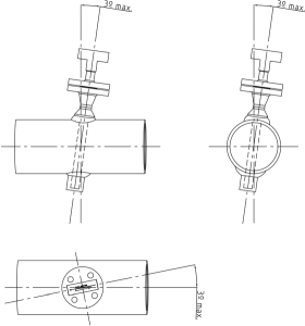
Use Chapter 11 to determine the proper KOBAR Pitot Tube straight run requirements.
For gas service, multiply the values from Chapter 11 by 1.5. Information contained in this manual applies to circular pipes only.
Straightening vanes may be used to reduce the required straight run length and will improve performance.
Row 6 in Chapter 11 applies to gate, globe, plug, and other throttling valves that are partially opened. If a “through-type” valve will remain open, use the values shown in Row 5. Refer to Row 6 for the straight run requirements of a KOBAR Pitot Tube located downstream of the control valve.
