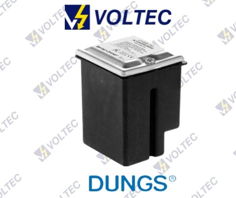
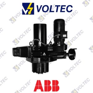
DUNGS Actuator DriveCP-9302-702
The CP-9302-702 electronic actuator drive processes a variable input signal from a controller to provide proportional control of an electric actuator. The CP-930-702 is preset for current input (4 – 20 mA) and has additional wiring for connection to an override switch for applications requiring an external override of the input signal. The CP-9302-702 is equipped with built-in jumpers and adjustable potentiometers, so that the type of input signal, deadband, input span, and start point may be readjusted in the field when necessary.
Description
DUNGS Actuator Drive CP-9302-702
Dungs Actuator DRIVE CP 9302 702
Electrical Ratings:-Power supplied by the actuator Input: 4 – 20 mA.
Electrical Connection:-1/2” NPT conduit knockout.
Deadband Adjustability (Hysteresis):-Factory set at 5 %, adjustable to 3 %.
Grounded Input:-Grounding either or both input wires will not cause damage.
Ambient Temperature:- 40 °F to +160 °F (-40 °C to + 71 °C).
Enviroment:-NEMA Type 4 (weathertight).
Series Operation:-No offset in control point when operated in tandem.
Open circuit Input:-Drives actuator to low.
DUNGS Actuator Drive CP-9302-702
Mounting-
1) Inspect the unit before installing, look for bent or broken parts or oil leaks from the actuator.
2) Use NEAM Type 4 compatible type connectors.
3) Observe the barrier that separates the line voltage terminals from the low voltage which controls the actuator motor.
4) All connections to the line voltage side of the barrier (L1 and L2, 1, 5, and 6 terminals) must be made with Class 1
wiring; connections to the remaining terminals can be Class 2 thermostat cables if desired.
5) Allow 6 inches (152 mm) clearance above the actuator wiring compartment.
6) Disconnect all power to the valves before wiring to prevent
electrical shock and equipment damage.
7) Do not exceed the electrical ratings given in the specifications and on the actuator.
8) Attach a flexible 1/2 conduit to the actuator.
9) Route the wires through the conduit.
10) Use 14 or 16-gauge wire for at least 75 °C (167 °F).
11) Connect the wiring to the appropriate screw terminals.
12) Remove the appropriate knockout on the side you wish to mount the sidebox.
14) Insert the sidebox into the actuator and leave the o-ring on the sidebox.
15) Secure the sidebox to the actuator with the conduit lock provided.
Installation-
1) Inspect the unit before installing, look for broken parts or leaks. Use NEMA Type 4 compatible type connectors.
2) Observe the barrier that separates the line voltage terminals from the low voltage which operates the actuator motor. All connections to the line voltage side of the barrier (L1 and L2, 1, 5, and 6 terminals) must be made with Class 1 wiring; connections to the remaining terminals can be Class 2 thermostat cables if desired.
3) Allow 6 inches (152 mm) clearance above the actuator wiring compartment.
4) Do not adjust the limit switch beyond 90° unless the standard slideware has been replaced with 180° slideware; do not adjust beyond 180° for proportioning control.
5) In some applications, a Flame Safeguard (FSG) may have one or two overriding circuits. One is a low-fire purge start and the other is a high-fire pre-purge. The function of the violet/white and violet wires is to provide an electrical connection so that the FSG can override, the temperature controller and drive the air damper actuator without a 4-mA signal. If such connections are not needed in the application, simply tape them off and safely stow away.
Adjustment-
If a CP-9302-702 requires adjustments to its start point or input span, make adjustments according to the following:
CP-9302-702 Adjustment (Preparation)
From the factory, the actuator is calibrated such that it drives to 90 degrees with 20 mA applied and 0 degrees with 4 mA applies. To reduce the 90-degree position or increase the 0-degree position, follow the procedure below.
Initial Setup-
1) Turn off all power and input signals to the actuator.
2) Remove the metal cover. This allows access to the potentiometers and the input/deadband jumpers.
3) Disconnect the drive’s yellow and blue leads from the controller.
4) Connect the drive’s leads to the corresponding lead on an instrument capable of producing 4 – 20 mA +/- 0.1 mA (current calibrator).
Minimum Position Calibration-
1) Apply power to the actuator, then turn on the “current calibrator”
2) Adjust the “current calibrator” until the mA input equals the desired zero-point current. This is typically 4 mA.
3) With the desired current input for the minimum position applied (typically 4 mA), adjust the zero point potentiometer so the actuator shaft drives to its zero point
(minimum position). It is best to adjust the start point potentiometer until the actuator shaft just starts to move off its zero point.
Maximum Position Calibration-
1) Apply power to the actuator, then turn on the “current calibrator”.
2) Adjust the “current calibrator” until the mA input equals the desired finish point (maximum position). This is typically 20 mA.
3) With the desired current input for the maximum position (typically 20 mA), the actuator will drive towards 90 degrees. Once the actuator stops, adjust the span potentiometer so the actuator shaft drives to the maximum position. It is best to adjust the span potentiometer until the actuator shaft just moves to its finish point.
4) Remove the current calibrator and turn off the power to the actuator. Then, reconnect the drive’s leads to the controller.
5) Reinstall the cover.
6) Reapply power to the actuator and turn on the controller.
Additional information
| Product Model | CP-9302-702 |
|---|---|
| Brand | DUNGS |
