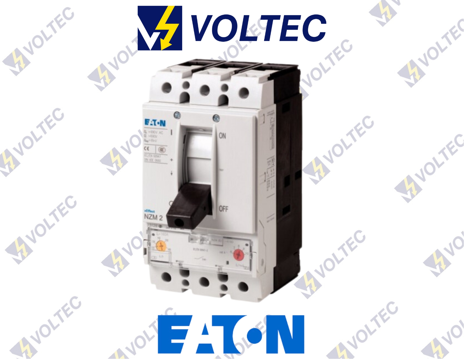
EATON MCCB NZMH2-A20-S1
Add to Wishlist
Add to Wishlist
EATON MCCB Digital NZM
ZMH2-A20-S1 – Circuit-breaker, 3p, 20A 1000V.
Description
EATON MCCB NZMH2-A20-S1
Eaton MCCB NZM (Digital NZM Moulded Case Circuit Breaker)
Circuit-breaker, 3p, 20A 1000V
| Part no. | NZMH2-A20-S1 |
Delivery program
| Product range | Circuit-breaker | ||
| Protective function | System and cable protection | ||
| Standard/Approval | IEC | ||
| Installation type | Fixed | ||
| Release system | Thermomagnetic release | ||
| Construction size | NZM2 | ||
| Description | NZM…S1 terminal type: NZM…XKSA cover required | ||
| Number of poles | 3 pole | ||
| Standard equipment | Screw connection | ||
| Rated current = rated uninterrupted current | In = Iu | A | 20 |
| Switching capacity | |||
| 1000 V 50/60 Hz | Icu | kA | 10 |
| Setting range | |||
| Overload trip | |||
| Ir | A | 15 – 20 | |
| Short-circuit releases | |||
| Non-delayed | Ii = In x … | 350 A fixed |
Technical data:-
Circuit-breakers
| Rated surge voltage invariability | Uimp | ||
| Main contacts | V | 8000 | |
| Auxiliary contacts | V | 6000 | |
| Rated operational voltage | Ue | V AC | 1000 |
| Rated current = rated uninterrupted current | In = Iu | A | 20 |
| Overvoltage category/pollution degree | III/3 | ||
| Rated insulation voltage | Ui | V | 1000 |
| Utilization category | A | ||
| Ambient temperature | |||
| Ambient temperature, storage | °C | – 40 – + 70 | |
| Operation | °C | -25 – +70 |
Rated short-circuit making capacity
| 240 V 50/60 Hz | Icm | kA | 330 |
| 400/415 V 50/60 Hz | Icm | kA | 330 |
| 440 V 50/60 Hz | Icm | kA | 286 |
| 525 V 50/60 Hz | Icm | kA | 105 |
| 690 V 50/60 H | Ic | kA | 40 |
| 1000 V 50/60 Hz | Icm | kA | 17 |
Rated short-time withstand current
| t = 0.3 s | Icw | kA | 1.9 |
| t = 1 s | Icw | kA | 1.9 |
| Lifespan, mechanical | Operations | 20000 | |
| Max. operating frequency | Ops/h | 120 | |
| Lifespan, mechanical: of which max |
Lifespan, electrical
| 1000 V 50/60 Hz | Operations | 3000 |
Terminal capacity
| Standard equipment | Screw connection | ||
| Round copper conductor | |||
| Box terminal | |||
| Solid | mm2 | 1 x (10 – 16)
2 x (6-16) |
|
| Stranded | mm2 | 1 x (25 – 185)
2 x (25-70) |
|
| Tunnel terminal | |||
| Solid | mm2 | 1 x 16 | |
| Stranded | |||
| Stranded | mm2 | 1 x (25 – 185) | |
| Bolt terminal and rear-side connection | |||
| Direct on the switch | |||
| Solid | mm2 | 1 x (10 – 16)
2 x (10 – 16) |
|
| Stranded | mm2 | 1 x (25 – 50)
2 x (25 – 50) |
|
| Al conductors, Cu cable | |||
| Tunnel terminal | |||
| Solid | mm2 | 1 x 16 | |
| Stranded | |||
| Stranded | mm2 | 1 x (25 – 185) 2) | |
| 2) Up to 240 mm² can be connected | |||
| Cu strip (number of segments x width x segment thickness) | |||
| Box terminal | |||
| min. | mm | 2 x 9 x 0.8 | |
| max. | mm | 10 x 16 x 0.8
(2x) 8 x 15.5 x 0,8 |
|
| Bolt terminal and rear-side connection | |||
| Flat copper strip, with holes | min. | mm | 2 x 16 x 0.8 |
| Flat copper strip, with holes | max. | mm | 10 x 16 x 0.8 |
| Copper busbar (width x thickness) | mm |
| Bolt terminal and rear-side connection | ||
| Screw connection | M8 | |
| Direct on the switch | ||
| min. | mm | 16 x 5 |
| max. | mm | 24 x 8 |
| Control cables | ||
| mm2 | 1 x (0.75 – 2.5)
2 x (0.75 – 1.5) |
MORE INFORMATION-PDF


