
YASKAWA A1000 Series AC Drive
Main Applications
A1000 is designed to handle a wide range of applications, including:
-Hoists, cranes, etc.
-Extruders, mold injectors
-Presses and other machine tooling
-Mixers, separators, grinders, other rotational applications
-Conveyors and other material transport
-Compressors
-Fan, supply pumps, hydraulic pumps, etc.
Description
YASKAWA A1000 Series AC Drive
High performance vector control AC drive
The A1000 is the premium AC drive from Yaskawa. It provides great operation reliability, environmental benefits, and energy savings as well as many other user-oriented operational features that make it a first-class choice.
- Encoderless operation of PM motors with full torque at zero speed
- Advanced Auto-Tuning functions to adjust automatically motor settings and analyze continuously changes during motor operation to achieve the highest machine performance
- Advanced energy-saving control technology which improves efficiency and machine productivity in combination with induction and synchronous motor operation
- Available with special features for a high-speed spindle, positioning, crane and hoist, electronic line shaft
Features
- Closed or open loop vector control for outstanding regulation, torque production, and position control capability.
- Continuous Auto-tuning optimizes performance by compensating for changes in motor temperature.
- High Frequency Injection enables high precision open loop control of Interior Permanent Magnet Motors.
- Fast acting current and voltage limiters help achieve continuous drive operation during periods of excessive demand.
- High Slip Braking reduces installation cost and the need for dynamic braking resistors
- Communication options for all major industrial networks provides high speed control and monitoring, reducing installation cost.
- DriveWizard computer software and Application Sets for easy configuration.
- Auxiliary Control Power Unit maximizes production time and efficiency by maintaining network communication while main power is removed.
- Embedded Safe Torque Off minimizes downtime for applications requiring occasional intervention (SIL CL2, PLd, Category 3).
- Embedded function blocks, programmable with DriveWorks EZ, provide additional application flexibility and the opportunity to eliminate separate controllers.
- USB Copy Unit and Keypad configuration storage provide speed and convenience for duplicate configuration of multiple drives.
- Removable terminal board with configuration storage provides convenience of configuration backup.
- Made with RoHS compliant materials.
- Integrated DC Reactor (standard on 30HP and larger) for input harmonic reduction.
- Kinetic Energy Braking allows drive to remain in control during momentary power losses.
- Integrated 12 Pulse version provides a cost effective solution for low harmonics.
- Flange version provides NEMA 12 backside integrity when mounting with heatsink external.
Specifications
|
Item
|
Specification
|
|---|---|
| Overload Capacity | 150% for 60 sec. (HD), 120% for 60 sec. (ND) |
| Output Frequency | 0~400 Hz (higher frequencies available with custom software) |
| Control Methods | Open and Closed Loop Current Vector; Open and Closed Loop V/f |
| Motor Types | Induction Surface Permanent Magnet (excluding 600V class) Interior Permanent Magnet (excluding 600V class) |
| Protective Design | IP20/NEMA1/FLANGE (NEMA 12 backside) |
| Ambient Operating Temperature | -10 to +50°C (Chassis Installation) -10 to +40°C (Chassis with zero side clearance, or Type 1) |
| Braking Transistor | Standard through 50HP (ND), 40HP (HD) |
| Global Certification | UL, CSA, CE, C-Tick, RoHS |
| Standard I/O | (8) multi-function digital inputs (24Vdc) (3) multi-function analog inputs (0 +/- 10 VDC, 4-20 mA) (1) multi-function pulse inputs (1) fault relay output (form C) (3) multi-function relay outputs (form A) (2) multi-function analog output (0 +/- 10 VDC, 4-20mA) (1) multi-function pulse output |
| I/O Expansion | 3 Analog Inputs -10 to +10V, 13 bit plus sign, 4 to 20mA 16 Digital Inputs (+24V for BCD speed reference) 2 Analog Outputs (-10 to +10V, 11 bit magnitude) 8 Digital Outputs (6 transistor, 2 relay) |
| Feedback | Incremental Absolute (Stegmann, Heidenhain EnDat, Resolver) Resolver |
| Network Communication | Built-in: Modbus RTU, RS-422/485, 115 kbpsOptional: EtherNet IP, DeviceNet, Modbus TCP/IP, PROFINET, PROFIBUS-DP, MECHATROLINK-II |
| Speed Control Range | 1500:1 Closed Loop Vector (IM and PM Motors) 200:1 Open Loop Vector (IM Motors) 100:1 Open Loop Vector (PM Motors) |
| Speed Control Accuracy | £ 0.02%: Closed Loop Vector; ≤ 0.2%; Open Loop Vector |
| Speed Response | ≥ 60 Hz: Closed Loop Vector; ≥ 10 Hz: Open Loop Vector |
| Torque Response | ≥ 300 Hz: Closed Loop Vector |
| Function Block Diagrams | Up to 100 connections, 1ms program scan time |
Models & Ratings
200-240V, 3-Phase, Protected Chassis/NEMA 1
|
Drive Model Number Standard
|
Normal Duty (ND)1
|
Heavy Duty (HD)1
|
Standard Enclosure
|
||
|---|---|---|---|---|---|
|
Rated Output Current (Amps)
|
Nominal HP2
|
Rated Output Current (Amps)
|
Nominal HP2
|
||
|
CIMR-AU2A0004FAA
|
3.5
|
3/4
|
3.2
|
3/4
|
NEMA 1
|
|
CIMR-AU2A0006FAA
|
6
|
1
|
5
|
1
|
|
|
CIMR-AU2A0008FAA
|
8
|
2
|
6.9
|
2
|
|
|
CIMR-AU2A0010FAA
|
9.6
|
2
|
8
|
2
|
NEMA 1
|
|
CIMR-AU2A0012FAA
|
12
|
3
|
11
|
3
|
|
|
CIMR-AU2A0018FAA
|
17.5
|
5
|
14
|
3
|
|
|
CIMR-AU2A0021FAA
|
21
|
7.5
|
17.5
|
5
|
NEMA 1
|
|
CIMR-AU2A0030FAA
|
30
|
10
|
25
|
7.5
|
|
|
CIMR-AU2A0040FAA
|
40
|
15
|
33
|
10
|
|
|
CIMR-AU2A0056FAA
|
56
|
20
|
47
|
15
|
NEMA 1
|
|
CIMR-AU2A0069FAA
|
69
|
25
|
60
|
20
|
|
|
CIMR-AU2A0081FAA
|
81
|
30
|
75
|
25
|
|
|
CIMR-AU2A0110FAA
|
110
|
40
|
85
|
30
|
NEMA 1
|
|
CIMR-AU2A0138FAA
|
138
|
50
|
115
|
40
|
|
|
CIMR-AU2A0169FAA
|
169
|
60
|
145
|
50
|
NEMA 1
|
|
CIMR-AU2A0211FAA
|
211
|
75
|
180
|
60
|
|
|
CIMR-AU2A0250AAA
|
250
|
100
|
215
|
75
|
Protected Chassis
|
|
CIMR-AU2A0312AAA
|
312
|
125
|
283
|
100
|
|
|
CIMR-AU2A0360AAA
|
360
|
150
|
346
|
125
|
Protected Chassis
|
| CIMR-AU2A0415AAA | 415 | 175 | 415 | 150 | |
-
Normal Duty overload current rating is 120% of rated output current for 60 seconds; Heavy Duty overload current rating is 150% of rated output current for 60 seconds
-
Horsepower rating is based on standard NEMA B 4-pole motor design as represented in NEC table 430.150 Full-Load Current, Three-Phase Alternating Current Motors. Also, listed power ratings assumes three-phase input. For single-phase input applications, consult Manual Supplement TOEPYEASUP03 for proper sizing.
200-240V, 3-Phase, Flange
|
Drive Model Number Flange1
|
Normal Duty (ND)2
|
Heavy Duty (HD)2
|
Enclosure1
|
||
|---|---|---|---|---|---|
|
Rated Output Current (Amps)
|
Nominal HP3
|
Rated Output Current (Amps)
|
Nominal HP3
|
||
|
CIMR-AU2A0004UAA
|
3.5
|
3/4
|
3.2
|
3/4
|
Flange
|
|
CIMR-AU2A0006UAA
|
6
|
1
|
5
|
1
|
|
|
CIMR-AU2A0008UAA
|
8
|
2
|
6.9
|
2
|
|
|
CIMR-AU2A0010UAA
|
9.6
|
3
|
8
|
2
|
Flange
|
|
CIMR-AU2A0012UAA
|
12
|
3
|
11
|
3
|
|
|
CIMR-AU2A0018UAA
|
17.5
|
5
|
14
|
3
|
|
|
CIMR-AU2A0021UAA
|
21
|
7.5
|
17.5
|
5
|
Flange
|
|
CIMR-AU2A0030UAA
|
30
|
10
|
25
|
7.5
|
|
|
CIMR-AU2A0040UAA
|
40
|
15
|
33
|
10
|
|
|
CIMR-AU2A0056UAA
|
56
|
20
|
47
|
15
|
Flange
|
|
CIMR-AU2A0069UAA
|
69
|
25
|
60
|
20
|
|
|
CIMR-AU2A0081UAA
|
81
|
30
|
75
|
25
|
|
|
CIMR-AU2A0110UAA
|
110
|
40
|
85
|
30
|
Flange
|
|
CIMR-AU2A0138UAA
|
138
|
50
|
115
|
40
|
|
|
CIMR-AU2A0169UAA
|
169
|
60
|
145
|
50
|
|
|
CIMR-AU2A0211UAA
|
211
|
75
|
180
|
60
|
Flange
|
|
CIMR-AU2A0250UAA
|
250
|
100
|
215
|
75
|
|
|
CIMR-AU2A0312UAA
|
312
|
125
|
283
|
100
|
|
|
CIMR-AU2A0360UAA
|
360
|
150
|
346
|
125
|
Flange
|
|
CIMR-AU2A0415UAA
|
415
|
175
|
415
|
150
|
|
-
Standard Enclosure can be conventionally mounted, or heatsink external (kit required for models CIMR-AU2A081FAA and smaller). Flange Enclosure includes special factory-installed gasketing and flange to provide NEMA 12 backside integrity when mounting heatsink external.
-
Normal Duty overload current rating is 120% of rated output current for 60 seconds; Heavy Duty overload current rating is 150% of rated output current for 60 seconds
-
Horsepower rating is based on standard NEMA B 4-pole motor design as represented in NEC table 430. 150 Full-Load Current, Three-Phase Alternating Current Motors
240V, Single-Phase Input, (208-230V Three-Phase Output)
|
Drive Model Number 1, 2, 3
|
Single Phase Input – Sizing Method A (A) (continuous full power)
|
Single Phase Input – Sizing Method B (B) (86% max power of connected motor size)
|
||||
|---|---|---|---|---|---|---|
|
Without Additional Reactor
|
With Additional Reactor
|
|||||
| Motor Amps | Motor Size (HP) | Motor Amps | Motor Size (HP) |
Motor Amps
|
Motor Size (HP)
|
|
|
CIMR-AU2A0004FAA
|
1.7
|
1/3
|
2.4
|
1/2
|
2.4
|
1/2
|
|
CIMR-AU2A0006FAA
|
3.5
|
3/4
|
3.5
|
3/4
|
4.6
|
1
|
|
CIMR-AU2A0008FAA
|
4.6
|
1
|
4.6
|
1
|
4.6
|
1
|
|
CIMR-AU2A0010FAA
|
4.6
|
1
|
4.6
|
1
|
6.6
|
1.5
|
|
CIMR-AU2A0012FAA
|
6.6
|
1.5
|
7.5
|
2
|
7.5
|
2
|
|
CIMR-AU2A0018FAA
|
7.5
|
2
|
10.6
|
3
|
10.6
|
3
|
|
CIMR-AU2A0021FAA
|
7.5
|
2
|
10.6
|
3
|
10.6
|
3
|
|
CIMR-AU2A0030FAA
|
10.6
|
3
|
10.6
|
3
|
17.0
|
5
|
|
CIMR-AU2A0040FAA
|
10.6
|
3
|
17
|
5
|
17.0
|
5
|
|
CIMR-AU2A0056FAA
|
17
|
5
|
24
|
7.5
|
24.0
|
7.5
|
|
CIMR-AU2A0069FAA
|
24
|
7.5
|
31
|
10
|
31.0
|
10
|
|
CIMR-AU2A0081FAA
|
31
|
10
|
46
|
15 |
46
|
15
|
|
CIMR-AU2A0110FAA
|
31
|
10
|
31
|
10 |
46
|
15
|
|
CIMR-AU2A0138FAA
|
46
|
15
|
46
|
15
|
59
|
20
|
|
CIMR-AU2A0169FAA
|
59
|
20
|
59
|
20
|
75
|
25
|
|
CIMR-AU2A0211FAA
|
75
|
25
|
75
|
25
|
88
|
30
|
|
CIMR-AU2A0250AAA
|
88
|
30
|
88
|
30
|
114
|
40
|
|
CIMR-AU2A0312AAA
|
114
|
40
|
114
|
40
|
143
|
50
|
|
CIMR-AU2A0360AAA
|
143
|
50
|
143
|
50
|
169
|
60
|
| CIMR-AU2A0415AAA |
169
|
60
|
169
|
60
|
211
|
75
|
-
Standard Enclosure can be conventionally mounted, or heatsink external (kit required for models CIMR-AU2A0081FAA and smaller). Flange Enclosure includes special factory-installed gasketing and flange to provide NEMA 12 backside integrity when mounting heatsink external.
-
Only models ending in FAA (CIMR-AU2A0211FAA and smaller) come standard with NEMA 1 End Cap Kits. Separately sold kits are available for larger models.
-
For Flange Drives, use the sizing method above to determine proper drive size. Use selected model numbers with “UAA” suffix instead of “FAA” or “AAA” suffix.
A. Use single phase input sizing method A for applications requiring more than 86% motor power. When sizing with additional reactor, consult factory. Caution: Adding more impedance than specified will degrade performance.
B. Use single phase input sizing method B for applications requiring a maximum of 86% motor power.
380-480V, 3-Phase, Protected Chassis/NEMA 1
|
Drive Model Number Standard
|
Normal Duty (ND)1
|
Heavy Duty (HD)1
|
Standard Enclosure
|
||
|---|---|---|---|---|---|
|
Rated Output Current (Amps)
|
Nominal HP2
|
Rated Output Current (Amps)
|
Nominal HP2
|
||
|
CIMR-AU4A0002FAA
|
2.1
|
3/4 & 1
|
1.8
|
3/4
|
NEMA 1
|
|
CIMR-AU4A0004FAA
|
4.1
|
2
|
3.4
|
1 & 2
|
|
|
CIMR-AU4A0005FAA
|
5.4
|
3
|
4.8
|
3
|
|
|
CIMR-AU4A0007FAA
|
6.9
|
4
|
5.5
|
3
|
NEMA 1
|
|
CIMR-AU4A0009FAA
|
8.8
|
5
|
7.2
|
4
|
|
|
CIMR-AU4A0011FAA
|
11.1
|
7.5
|
9.2
|
5
|
|
|
CIMR-AU4A0018FAA
|
17.5
|
10
|
14.8
|
7.5 & 10
|
NEMA 1
|
|
CIMR-AU4A0023FAA
|
23
|
15
|
18
|
10
|
|
|
CIMR-AU4A0031FAA
|
31
|
20
|
24
|
15
|
|
|
CIMR-AU4A0038FAA
|
38
|
25
|
31
|
20
|
NEMA 1
|
|
CIMR-AU4A0044FAA
|
44
|
30
|
39
|
25 & 30
|
|
|
CIMR-AU4A0058FAA
|
58
|
40
|
45
|
30
|
|
|
CIMR-AU4A0072FAA
|
72
|
50
|
60
|
40
|
NEMA 1
|
|
CIMR-AU4A0088FAA
|
88
|
60
|
75
|
50 & 60
|
|
|
CIMR-AU4A0103FAA
|
103
|
75
|
91
|
60
|
|
|
CIMR-AU4A0139FAA
|
139
|
100
|
112
|
75
|
NEMA 1
|
|
CIMR-AU4A0165FAA
|
165
|
125
|
150
|
100
|
|
|
CIMR-AU4A0208AAA
|
208
|
150
|
180
|
125 & 150
|
Protected Chassis
|
|
CIMR-AU4A0250AAA
|
250
|
200
|
216
|
150
|
|
|
CIMR-AU4A0296AAA
|
296
|
250
|
260
|
200
|
|
|
CIMR-AU4A0362AAA
|
362
|
300
|
304
|
250
|
Protected Chassis
|
|
CIMR-AU4A0414AAA
|
414
|
350
|
370
|
300
|
|
|
CIMR-AU4A0515AAA
|
515
|
400
|
450
|
350
|
Protected Chassis
|
|
CIMR-AU4A0675AAA
|
675
|
500
|
605
|
400-500
|
|
|
CIMR-AU4A0930AAA
|
930
|
700-800
|
810
|
600-700
|
Protected Chassis
|
|
CIMR-AU4A1200AAA
|
1200
|
900-1000
|
1090
|
800-900
|
|
-
Normal Duty overload current rating is 120% of rated output current for 60 seconds; Heavy Duty overload current rating is 150% of rated output current for 60 seconds
-
Horsepower rating is based on standard NEMA B 4-pole motor design as represented in NEC table 430.150 Full-Load Current, Three-Phase Alternating Current Motors. Also, listed power ratings assumes three-phase input. For single-phase input applications, consult Manual Supplement TOEPYEASUP03 for proper sizing.
380-480V, 3-Phase, Flange
|
Drive Model Number Flange1
|
Normal Duty (ND)2
|
Heavy Duty (HD)2
|
Enclosure1
|
||
|---|---|---|---|---|---|
|
Rated Output Current (Amps)
|
Nominal HP3
|
Rated Output Current (Amps)
|
Nominal HP3
|
||
|
CIMR-AU4A0002UAA
|
2.1
|
1
|
1.8
|
3/4
|
Flange
|
|
CIMR-AU4A0004UAA
|
4.1
|
2
|
3.4
|
1 & 2
|
|
|
CIMR-AU4A0005UAA
|
5.4
|
3
|
4.8
|
3
|
|
|
CIMR-AU4A0007UAA
|
6.9
|
4
|
5.5
|
3
|
Flange
|
|
CIMR-AU4A0009UAA
|
8.8
|
5
|
7.2
|
5
|
|
|
CIMR-AU4A0011UAA
|
11.1
|
7.5
|
9.2
|
5
|
|
|
CIMR-AU4A0018UAA
|
17.5
|
10
|
14.8
|
7.5 & 10
|
Flange
|
|
CIMR-AU4A0023UAA
|
23
|
15
|
18
|
10
|
|
|
CIMR-AU4A0031UAA
|
31
|
20
|
24
|
15
|
|
|
CIMR-AU4A0038UAA
|
38
|
25
|
31
|
20
|
Flange
|
|
CIMR-AU4A0044UAA
|
44
|
30
|
39
|
25 & 30
|
|
|
CIMR-AU4A0058UAA
|
58
|
40
|
45
|
30
|
|
|
CIMR-AU4A0072UAA
|
72
|
50
|
60
|
40
|
Flange
|
|
CIMR-AU4A0088UAA
|
88
|
60
|
75
|
50 & 60
|
|
|
CIMR-AU4A0103UAA
|
103
|
75
|
91
|
60
|
|
|
CIMR-AU4A0139UAA
|
139
|
100
|
112
|
75
|
Flange
|
|
CIMR-AU4A0165UAA
|
165
|
125
|
150
|
100
|
|
|
CIMR-AU4A0208UAA
|
208
|
150
|
180
|
125 & 150
|
Flange
|
|
CIMR-AU4A0250UAA
|
250
|
200
|
216
|
150
|
|
|
CIMR-AU4A0296UAA
|
296
|
250
|
260
|
200
|
|
|
CIMR-AU4A0362UAA
|
362
|
300
|
304
|
250
|
Flange
|
|
CIMR-AU4A0414UAA
|
414
|
350
|
370
|
300
|
|
|
CIMR-AU4A0515UAA
|
515
|
400
|
450
|
350
|
Flange
|
|
CIMR-AU4A0675UAA
|
675
|
500
|
605
|
400-500
|
|
|
CIMR-AU4A0930UAA4
|
930
|
700-800
|
810
|
600-700
|
Flange
|
|
CIMR-AU4A1200UAA4
|
1200
|
900-1000
|
1090
|
800-900
|
|
-
Standard Enclosure can be conventionally mounted, or heatsink external (kit required for models CIMR-AU2A081FAA and smaller). Flange Enclosure includes special factory-installed gasketing and flange to provide NEMA 12 backside integrity when mounting heatsink external.
-
Normal Duty overload current rating is 120% of rated output current for 60 seconds; Heavy Duty overload current rating is 150% of rated output current for 60 seconds
-
Horsepower rating is based on standard NEMA B 4-pole motor design as represented in NEC table 430. 150 Full-Load Current, Three-Phase Alternating Current Motors
-
Models CIMR-AU4A0930UAA and CIMR-AU4A1200UAA must be used with semiconductor input fuses and must be fed by a power source that has ground fault protection. A supplementary ground fault protection device can be added between the drive and the power source to address this requirement.
380-480V, 3-Phase,12-Pulse
|
Drive Model Number 12-Pulse Flange1
|
Normal Duty (ND)2
|
Heavy Duty (HD)2
|
Enclosure1
|
||
|---|---|---|---|---|---|
|
Rated Output Current (Amps)
|
Nominal HP3
|
Rated Output Current (Amps)
|
Nominal HP3
|
||
|
CIMR-AU4T0058UAA
|
58
|
40
|
45
|
30
|
Flange
|
|
CIMR-AU4T0072UAA
|
72
|
50
|
60
|
40
|
|
|
CIMR-AU4T0088UAA
|
88
|
60
|
75
|
50 & 60
|
Flange
|
|
CIMR-AU4T0103UAA
|
103
|
75
|
91
|
60
|
|
|
CIMR-AU4T0139UAA
|
139
|
100
|
112
|
75
|
Flange
|
|
CIMR-AU4T0165UAA
|
165
|
125
|
150
|
100
|
|
|
CIMR-AU4T0208UAA
|
208
|
150
|
180
|
125 & 150
|
Flange
|
|
CIMR-AU4T0250UAA
|
250
|
200
|
216
|
150
|
|
|
CIMR-AU4T0296UAA
|
296
|
250
|
260
|
200
|
|
|
CIMR-AU4T0362UAA
|
362
|
300
|
304
|
250
|
Flange
|
|
CIMR-AU4T0414UAA
|
414
|
350
|
370
|
300
|
|
|
CIMR-AU4T0515UAA
|
515
|
400
|
450
|
350
|
Flange
|
|
CIMR-AU4T0675UAA
|
675
|
500-600
|
605
|
400-500
|
|
|
See note 4
|
930
|
700-800
|
810
|
600-700
|
Fnlage
|
|
See note 4
|
1200
|
900-1000
|
1090
|
800-900
|
|
-
Flange Enclosure includes special factory-installed gasketing and flange to provide NEMA 12 backside integrity when mounting heatsink external. Flange parts can be removed if conventional mounting is desired.
-
Normal Duty overload current rating is 120% of rated output current for 60 seconds; Heavy Duty overload current rating is 150% of rated output current for 60 seconds.
-
Horsepower rating is based on standard NEMA B 4-pole motor design as represented in NEC table 430.150 Full-Load Current, Three-Phase Alternating Current Motors.
-
Models CIMR-AU4A0930xxx and CIMR-AU4A1200xxx are user configurable for either 6-Pulse (3-Phase) or 12-Pulse (6-Phase) input. See Standard 480V for model numbers.>
480V, Single-Phase Input, (460V Three-Phase Output)
|
Drive Model Number 1, 2, 3
|
Drive Model Number (NEMA 1 Compatible)
|
Single Phase Input – Sizing Method A (A) (continuous full power)
|
Single Phase Input – Sizing Method B (B) (86% max power of connected motor size)
|
||||
|---|---|---|---|---|---|---|---|
|
Without Additional Reactor
|
With Additional Reactor
|
||||||
| Motor Amps | Motor Size (HP) | Motor Amps | Motor Size (HP) |
Motor Amps
|
Motor Size (HP)
|
||
|
CIMR-AU4A0002FAA
|
0.8
|
1/3
|
1.1
|
1/2
|
0.8
|
1/3
|
|
|
CIMR-AU4A0004FAA
|
1.6
|
3/4
|
2.1
|
1
|
2.1
|
1
|
|
|
CIMR-AU4A0005FAA
|
2.1
|
1
|
3.0
|
1.5
|
3.0
|
1.5
|
|
|
CIMR-AU4A0007FAA
|
3.0
|
1.5
|
3.4
|
2
|
3.4
|
2
|
|
|
CIMR-AU4A0009FAA
|
3.4
|
2
|
4.8
|
3
|
4.8
|
3
|
|
|
CIMR-AU4A0011FAA
|
3.4
|
2
|
4.8
|
3
|
4.8
|
3
|
|
|
CIMR-AU4A0018FAA
|
4.8
|
3
|
4.8
|
3
|
7.6
|
5
|
|
|
CIMR-AU4A0023FAA
|
4.8
|
3
|
7.6
|
5
|
7.6
|
5
|
|
|
CIMR-AU4A0031FAA
|
11
|
7.5
|
11
|
7.5
|
14.0
|
10
|
|
|
CIMR-AU4A0038FAA
|
11
|
7.5
|
14
|
10
|
14.0
|
10
|
|
|
CIMR-AU4A0044FAA
|
14
|
10
|
14
|
10
|
21.0
|
15
|
|
|
CIMR-AU4A0058FAA
|
21
|
15
|
21
|
15
|
27.0
|
20
|
|
|
CIMR-AU4A0072FAA
|
27
|
20
|
27
|
20
|
34.0
|
25
|
|
|
CIMR-AU4A0088FAA
|
27
|
20
|
27
|
20
|
34.0
|
25
|
|
|
CIMR-AU4A0103FAA
|
27
|
20
|
27
|
20
|
34.0
|
25
|
|
|
CIMR-AU4A0139FAA
|
52
|
40
|
52
|
40
|
65.0
|
50
|
|
|
CIMR-AU4A0165FAA
|
52
|
40
|
52
|
40
|
65.0
|
50
|
|
|
CIMR-AU4A0208AAA
|
65
|
50
|
65
|
50
|
77.0
|
60
|
|
|
CIMR-AU4A0250AAA
|
77
|
60
|
77
|
60
|
96
|
75
|
|
|
CIMR-AU4A0296AAA
|
96
|
75
|
96
|
75
|
124
|
100
|
|
|
CIMR-AU4A0362AAA
|
124
|
100
|
124
|
100
|
156
|
125
|
|
|
CIMR-AU4A0414AAA
|
CIMR-UUX000679
|
156
|
125
|
156
|
125
|
180
|
150
|
|
CIMR-AU4A0515AAA
|
CIMR-UUX000680
|
156
|
125
|
156
|
125
|
180
|
150
|
|
CIMR-AU4A0675AAA
|
CIMR-UUX000681
|
180
|
150
|
180
|
150
|
240
|
200
|
-
Standard Enclosure can be conventionally mounted, or heatsink external (kit required for models CIMR-AU2A0081FAA and smaller). Flange Enclosure includes special factory-installed gasketing and flange to provide NEMA 12 backside integrity when mounting heatsink external.
-
Only models ending in FAA (CIMR-AU2A0211FAA and smaller) come standard with NEMA 1 End Cap Kits. Separately sold kits are available for larger models.
-
For Flange Drives, use the sizing method above to determine proper drive size. Use selected model numbers with “UAA” suffix instead of “FAA” or “AAA” suffix.
-
Use single phase input sizing method A for applications requiring more than 86% motor power. When sizing with additional reactor, consult factory. Caution: Adding more impedance than specified will degrade performance.
-
Use single phase input sizing method B for applications requiring a maximum of 86% motor power.
500-600V, 3-Phase, Protected Chassis/NEMA 1
|
Drive Model Number Standard
|
Normal Duty (ND)1
|
Heavy Duty (HD)1
|
Standard Enclosure
|
||
|---|---|---|---|---|---|
|
Rated Output Current (Amps)
|
Nominal HP2
|
Rated Output Current (Amps)
|
Nominal HP2
|
||
|
CIMR-AU5A0003FAA
|
2.7
|
1 & 2
|
1.7
|
1
|
NEMA 1
|
|
CIMR-AU5A0004FAA
|
3.9
|
3
|
3.5
|
2
|
|
|
CIMR-AU5A0006FAA
|
6.1
|
5
|
4.1
|
3
|
|
|
CIMR-AU5A0009FAA
|
9
|
7.5
|
6.3
|
5
|
NEMA 1
|
|
CIMR-AU5A0011FAA
|
11
|
10
|
9.8
|
7.5
|
|
|
CIMR-AU5A0017FAA
|
17.5
|
15
|
12.5
|
10
|
|
|
CIMR-AU5A0022FAA
|
22
|
20
|
17
|
15
|
NEMA 1
|
|
CIMR-AU5A0027FAA
|
27
|
25
|
22
|
20
|
|
|
CIMR-AU5A0032FAA
|
32
|
30
|
27
|
25
|
|
|
CIMR-AU5A0041FAA
|
41
|
40
|
32
|
30
|
NEMA 1
|
|
CIMR-AU5A0052FAA
|
52
|
50
|
41
|
40
|
|
|
CIMR-AU5A0062FAA
|
62
|
60
|
52
|
50
|
|
|
CIMR-AU5A0077FAA
|
77
|
75
|
62
|
60
|
NEMA 1
|
|
CIMR-AU5A0099FAA
|
99
|
100
|
77
|
75
|
|
|
CIMR-AU5A0125AAA
|
125
|
125
|
99
|
100
|
Protected Chassis
|
|
CIMR-AU5A0145AAA
|
145
|
150
|
130
|
125
|
|
|
CIMR-AU5A0192AAA
|
192
|
200
|
172
|
150
|
Protected Chassis
|
|
CIMR-AU5A0242AAA
|
242
|
250
|
200
|
200
|
|
-
Normal Duty overload current rating is 120% of rated output current for 60 seconds; Heavy Duty overload current rating is 150% of rated output current for 60 seconds
-
Horsepower rating is based on standard NEMA B 4-pole motor design as represented in NEC table 430.150 Full-Load Current, Three-Phase Alternating Current Motors. Also, listed power ratings assumes three-phase input. For single-phase input applications, consult Manual Supplement TOEPYEASUP03 for proper sizing.
500-600V, 3-Phase, Flange
|
Drive Model Number Flange1
|
Normal Duty (ND)2
|
Heavy Duty (HD)2
|
Enclosure1
|
||
|---|---|---|---|---|---|
|
Rated Output Current (Amps)
|
Nominal HP3
|
Rated Output Current (Amps)
|
Nominal HP3
|
||
|
CIMR-AU5A0003UAA
|
2.7
|
1 & 2
|
1.7
|
1
|
Flange
|
|
CIMR-AU5A0004UAA
|
3.9
|
3
|
3.5
|
2
|
|
|
CIMR-AU5A0006UAA
|
6.1
|
5
|
4.1
|
3
|
|
|
CIMR-AU5A0009UAA
|
9
|
7.5
|
6.3
|
5
|
Flange
|
|
CIMR-AU5A0011UAA
|
11
|
10
|
9.8
|
7.5
|
|
|
CIMR-AU5A0017UAA
|
17.5
|
15
|
12.5
|
10
|
|
|
CIMR-AU5A0022UAA
|
22
|
20
|
17
|
15
|
Flange
|
|
CIMR-AU5A0027UAA
|
27
|
25
|
22
|
20
|
|
|
CIMR-AU5A0032UAA
|
32
|
30
|
27
|
25
|
|
|
CIMR-AU5A0041UAA
|
41
|
40
|
32
|
30
|
Flange
|
|
CIMR-AU5A0052UAA
|
52
|
50
|
41
|
40
|
|
|
CIMR-AU5A0062UAA
|
62
|
60
|
52
|
50
|
|
|
CIMR-AU5A0077UAA
|
77
|
75
|
62
|
60
|
Flange
|
|
CIMR-AU5A0099UAA
|
99
|
100
|
77
|
75
|
|
|
CIMR-AU5A0125UAA
|
125
|
125
|
99
|
100
|
Flange
|
|
CIMR-AU5A0145UAA
|
145
|
150
|
130
|
125
|
|
|
CIMR-AU5A0192UAA
|
192
|
200
|
172
|
150
|
Flange
|
|
CIMR-AU5A0242UAA
|
242
|
250
|
200
|
200
|
|
-
Standard Enclosure can be conventionally mounted, or heatsink external (kit required for models CIMR-AU2A081FAA and smaller). Flange Enclosure includes special factory-installed gasketing and flange to provide NEMA 12 backside integrity when mounting heatsink external.
-
Normal Duty overload current rating is 120% of rated output current for 60 seconds; Heavy Duty overload current rating is 150% of rated output current for 60 seconds
-
Horsepower rating is based on standard NEMA B 4-pole motor design as represented in NEC table 430. 150 Full-Load Current, Three-Phase Alternating Current Motors
600V, Single-Phase Input, (575V Three-Phase Output)
|
Drive Model Number 1, 2, 3
|
Single Phase Input – Sizing Method A (A) (continuous full power)
|
Single Phase Input – Sizing Method B (B) (86% max power of connected motor size)
|
||||
|---|---|---|---|---|---|---|
|
Without Additional Reactor
|
With Additional Reactor
|
|||||
| Motor Amps | Motor Size (HP) | Motor Amps | Motor Size (HP) |
Motor Amps
|
Motor Size (HP)
|
|
|
CIMR-AU5A0003FAA
|
1.7
|
1
|
2.4
|
1.5
|
1.7
|
1
|
|
CIMR-AU5A0004FAA
|
2.4
|
1.5
|
2.7
|
2
|
2.7
|
2
|
|
CIMR-AU5A0006FAA
|
2.7
|
2
|
3.9
|
3
|
3.9
|
3
|
|
CIMR-AU5A0009FAA
|
3.9
|
3
|
6.1
|
5
|
6.1
|
5
|
|
CIMR-AU5A0011FAA
|
2.7
|
2
|
3.9
|
3
|
3.9
|
3
|
|
CIMR-AU5A0017FAA
|
6.1
|
5
|
6.1
|
5
|
9.0
|
7.5
|
|
CIMR-AU5A0022FAA
|
6.1
|
5
|
7.5
|
9.0
|
9.0
|
7.5
|
|
CIMR-AU5A0027FAA
|
9.0
|
7.5
|
11
|
10
|
11.0
|
10
|
|
CIMR-AU5A0032FAA
|
9.0
|
7.5
|
11
|
10
|
11.0
|
10
|
|
CIMR-AU5A0041FAA
|
17
|
15
|
17
|
15
|
22.0
|
20
|
|
CIMR-AU5A0052FAA
|
17
|
15
|
17
|
15
|
22.0
|
20
|
|
CIMR-AU5A0062FAA
|
27
|
25
|
27
|
25
|
32.0
|
30
|
|
CIMR-AU5A0077FAA
|
32
|
30
|
32
|
30
|
41
|
40
|
|
CIMR-AU5A0099FAA
|
32
|
30
|
32
|
30
|
41
|
40
|
|
CIMR-AU5A0125AAA
|
52
|
50
|
52
|
50
|
62
|
60
|
|
CIMR-AU5A0145AAA
|
52
|
50
|
52
|
50
|
62
|
60
|
|
CIMR-AU5A0192AAA
|
77
|
75
|
77
|
75
|
99
|
100
|
|
CIMR-AU5A0242AAA
|
77
|
75
|
77
|
75
|
99
|
100
|
-
Standard Enclosure can be conventionally mounted, or heatsink external (kit required for models CIMR-AU2A0081FAA and smaller). Flange Enclosure includes special factory-installed gasketing and flange to provide NEMA 12 backside integrity when mounting heatsink external.
-
Only models ending in FAA (CIMR-AU2A0211FAA and smaller) come standard with NEMA 1 End Cap Kits. Separately sold kits are available for larger models.
-
For Flange Drives, use the sizing method above to determine proper drive size. Use selected model numbers with “UAA” suffix instead of “FAA” or “AAA” suffix.
-
1. A. Use single phase input sizing method A for applications requiring more than 86% motor power. When sizing with additional reactor, refer to “Reactors for Single Phase Input” section of this price book. Caution: Adding more impedance than specified will degrade performance.
-
-
-
2 B. Use single phase input sizing method B for applications requiring a maximum of 86% motor power.
-
Model Number Key:
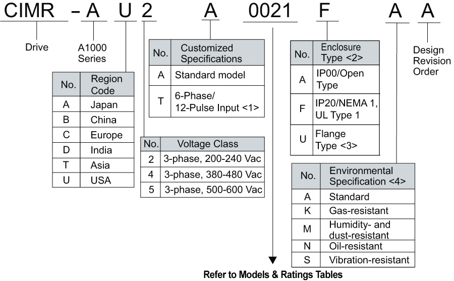
<1> Refer to manual TOEPYAIA1U02 for information on 12-pulse models.
<2> Refer to Drive Models and Enclosure types on page 39 of the technical manual (Doc# SIEPC71061641) for differences regarding enclosure protection types and component descriptions.
<3> Provides method of mounting drive with backside (heatsink) external to enclosure, with NEMA 12, UL Type 12 integrity.
<4> Drives with these specifications do not guarantee complete protection for the environmental conditions indicated.
Market Demands with A1000 Series
Yaskawa predicts continued market expansion with the growing need for more energy efficient production in addition to the already present demand for variable-speed drives. Market demands have moved increasingly towards greater energy conservation and even more compact installations. This is evident in the recent employment of synchronous motors to HVAC systems, and for the first time, high performance drives to fan and pump applications. These trends have led to greater demands for inverter drives that are capable of controlling synchronous motors as well as high performance operation and functionality.
In response to the industry, Yaskawa has stepped ahead of the competition by launching the third edition to its 1000 Series, high performance vector control A1000. Referred to as Yaskawa’s “Ace Drive”, A1000 handles not only induction motors, but the same drive also runs permanent magnet motors. The 1000 Series product line is loaded with cutting-edge functionality and powerful cost performance to answer market demands.
Datasheet: PDF


