
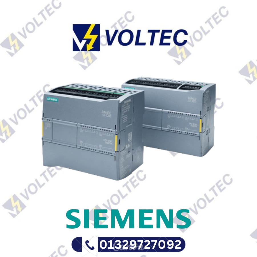
SIEMENS Fail-safe CPU | S7-1200 series | 6ES7215-1AF40-0XB0
- Supply Voltage: 24 V DC
- Input current: 500 mA
- Output current: 1600 mA
For Price Call: 01326 708335
Email: sales@voltecbd.com
Description
SIEMENS Fail-safe CPU | S7-1200 series | 6ES7215-1AF40-0XB0
SIEMENS Fail-safe CPU
SIEMENS Fail-safe CPU supplier in Bangladesh
Fail-safe CPUs
The fail-safe SIMATIC S7-1200 Controllers are based on the S7-1200 standard CPUs and offer additional safety-related functions.
They can be used for safety-related tasks according to IEC 61508 up to SIL 3 and ISO 13849-1 up to PL e.
Safety-related programs are created in the TIA Portal. The STEP 7 Safety engineering tool offers commands, operations and blocks for safety-related programs in the LAD and FBD languages. To this end, there is a library with pre-configured blocks for safety-related functions certified by the German Technical Inspectorate (TÜV).
- Standard controller with integrated safety functions:
- Standardized and convenient diagnostic functions for standard and safety
- Uniform symbols, data consistency, …
- Modular system with scalable range of CPUs and expandable I/O quantity structure:
- One engineering for standard and fail-safe automation
- Use of the standard I/O modules together with the fail-safe I/O modules in the central system
- Integrated standard PROFINET functionalities for PROFINET controllers and PROFINET iDevice services
- Connection of distributed standard I/O via fieldbus such as PROFINET or PROFIBUS
- F-library certified by the German Technical Inspectorate (TÜV) for all common safety functions
- Free programming of the safety logic using FBD and LAD
- Standard-compliant printout of the F-program
- One integrated engineering for both standard and safety from S7-1200 to S7-300/400/1500 and WinAC RTX F:
- STEP 7 Safety Basic for easy engineering of the CPU 1200 FC
- STEP 7 Safety Advanced for the entire fail-safe SIMATIC S7 portfolio
- Integrated system diagnostics of the CPUs, for standard and safety:
- Consistent plain text display of system diagnostics information in the TIA Portal, HMI and web server
- Messages are updated even if the CPU is in STOP state
- System diagnostics integrated in the CPU firmware. Configuration by user not required
- The diagnostics is automatically updated on configuration changes.
- 2 fail-safe compact controllers with graded performances in the versions DC/DC/DC and DC/DC/relay
Technical details-
| General information | ||
| Product type designation | CPU 1215FC DC/DC/DC | |
| Firmware version | V4.7 | |
| Engineering with | ||
| ● Programming package | STEP 7 V20 or higher | |
| Supply voltage | ||
| Rated value (DC) | ||
| ● 24 V DC | Yes | |
| permissible range, lower limit (DC) | 20.4 V | |
| permissible range, upper limit (DC) | 28.8 V | |
| Reverse polarity protection | Yes | |
| Load voltage L+ | ||
| ● Rated value (DC) | 24 V | |
| ● permissible range, lower limit (DC) | 20.4 V | |
| ● permissible range, upper limit (DC) | 28.8 V | |
| Input current | ||
| Current consumption (rated value) | 500 mA; CPU only | |
| Current consumption, max. | 1 500 mA; CPU with all expansion modules | |
| Inrush current, max. | 12 A; at 28.8 V DC | |
| I²t | 0.5 A²·s | |
| Output current | ||
| for backplane bus (5 V DC), max. | 1 600 mA; Max. 5 V DC for SM and CM | |
| Encoder supply | ||
| 24 V encoder supply | ||
| ● 24 V | L+ minus 4 V DC min. | |
| Power loss | ||
| Power loss, typ. | 12 W | |
| Storage | ||
| Work memory | ||
| ● integrated | 250 kbyte | |
| Load memory | ||
| ● integrated | 4 Mbyte | |
| ● Plug-in (SIMATIC Memory Card), max. | with SIMATIC memory card | |
| Backup | ||
| ● present | Yes | |
| ● maintenance-free | Yes | |
| ● without battery | Yes | |
| CPU processing times | ||
| for bit operations, typ. | 0.08 µs; / instruction | |
| for word operations, typ. | 1.7 µs; / instruction | |
| for floating point arithmetic, typ. | 2.3 µs; / instruction | |
| CPU-blocks | ||
| Number of blocks (total) | DBs, FCs, FBs, counters and timers. The maximum number of addressable blocks ranges from 1 to 65535. There is no restriction, the entire working memory can be used | |
| OB | ||
| ● Number, max. | Limited only by RAM for code | |
| Data areas and their retentivity | ||
| Retentive data area (incl. timers, counters, flags), max. | 14 kbyte | |
| Flag | ||
| ● Size, max. | 8 kbyte; Size of bit memory address area | |
| Local data | ||
| ● per priority class, max. | 16 kbyte; Priority class 1 (program cycle): 16 KB, priority class 2 to 26: 6 KB | |
| Address area | ||
| Process image | ||
| ● Inputs, adjustable | 1 kbyte | |
| ● Outputs, adjustable | 1 kbyte | |
| Hardware configuration | ||
| Number of modules per system, max. | 3 comm. modules, 1 signal board, 8 signal modules | |
| ● number of expansion boards (SB, CB, BB) | 1 | |
| ● number of signal modules (SM) | 8 | |
| ● number of communications modules (CM) | 3 | |
| Time of day | ||
| Clock | ||
| ● Hardware clock (real-time) | Yes | |
| ● Backup time | 480 h; Typical | |
| ● Deviation per day, max. | ±60 s/month at 25 °C | |
| Digital inputs | ||
| Number of digital inputs | 14; Integrated | |
| ● of which inputs usable for technological functions | 6; HSC (High Speed Counting) | |
| Sourcing/sinking input | Yes | |
| Number of simultaneously controllable inputs | ||
| all mounting positions | ||
| — up to 40 °C, max. | 14 | |
| Input voltage | ||
| ● Rated value (DC) | 24 V | |
| ● for signal “0” | 5 V DC at 1 mA | |
| ● for signal “1” | 15 V DC at 2.5 mA | |
| Input delay (for rated value of input voltage) | ||
| for standard inputs | ||
| — parameterizable | 0.1 / 0.2 / 0.4 / 0.8 / 1.6 / 3.2 / 6.4 / 10.0 / 12.8 / 20.0 μs; 0.05 / 0.1 / 0.2 / 0.4 / 0.8 / 1.6 / 3.2 / 6.4 / 10.0 / 12.8 / 20.0 ms | |
| — at “0” to “1”, min. | 0.2 ms | |
| — at “0” to “1”, max. | 12.8 ms | |
| for interrupt inputs | ||
| — Parameterizable | Yes | |
| for technological functions | ||
| — Parameterizable | Single phase: 3 @ 100 kHz & 3 @ 30 kHz, differential: 3 @ 80 kHz & 3 @ 30 kHz | |
| Cable length | ||
| ● shielded, max. | 500 m; 50 m for technological functions | |
| ● unshielded, max. | 300 m; for technological functions: No | |
| Digital outputs | ||
| Number of digital outputs | 10 | |
| ● of which high-speed outputs | 4; 100 kHz Pulse Train Output | |
| Limitation of inductive shutdown voltage to | L+ (-48 V) | |
| Switching capacity of the outputs | ||
| ● with resistive load, max. | 0.5 A | |
| ● on lamp load, max. | 5 W | |
| Output voltage | ||
| ● for signal “0”, max. | 0.1 V; with 10 kOhm load | |
| ● for signal “1”, min. | 20 V | |
| Output current | ||
| ● for signal “1” rated value | 0.5 A | |
| ● for signal “0” residual current, max. | 0.1 mA | |
| Output delay with resistive load | ||
| ● “0” to “1”, max. | 1 µs | |
| ● “1” to “0”, max. | 5 µs | |
| Switching frequency | ||
| ● of the pulse outputs, with resistive load, max. | 100 kHz | |
| Relay outputs | ||
| ● Number of relay outputs | 0 | |
| Cable length | ||
| ● shielded, max. | 500 m | |
| ● unshielded, max. | 150 m | |
| Analog inputs | ||
| Number of analog inputs | 2 | |
| Input ranges | ||
| ● Voltage | Yes | |
| Input ranges (rated values), voltages | ||
| ● 0 to +10 V | Yes | |
| — Input resistance (0 to 10 V) | ≥100k ohms | |
| Cable length | ||
| ● shielded, max. | 100 m; twisted and shielded | |
| Analog outputs | ||
| Number of analog outputs | 2 | |
| Output ranges, current | ||
| ● 0 to 20 mA | Yes | |
| Analog value generation for the inputs | ||
| Integration and conversion time/resolution per channel | ||
| ● Resolution with overrange (bit including sign), max. | 10 bit | |
| ● Integration time, parameterizable | Yes | |
| ● Conversion time (per channel) | 625 µs | |
| Analog value generation for the outputs | ||
| Integration and conversion time/resolution per channel | ||
| ● Resolution with overrange (bit including sign), max. | 10 bit | |
| Encoder | ||
| Connectable encoders | ||
| ● 2-wire sensor | Yes | |
| Interfaces | ||
| Number of PROFINET interfaces | 1 | |
| 1. Interface | ||
| Interface type | PROFINET | |
| Isolated | Yes | |
| automatic detection of transmission rate | Yes | |
| Autonegotiation | Yes | |
| Autocrossing | Yes | |
| Interface types | ||
| ● RJ 45 (Ethernet) | Yes | |
| ● Number of ports | 2 | |
| ● integrated switch | Yes | |
| Protocols | ||
| ● PROFINET IO Controller | Yes | |
| ● PROFINET IO device | Yes | |
| ● SIMATIC communication | Yes | |
| ● Open IE communication | Yes; Optionally also encrypted | |
| ● Web server | Yes | |
| ● Media redundancy | Yes; as MRP client | |
| PROFINET IO Controller | ||
| ● Transmission rate, max. | 100 Mbit/s | |
| Services | ||
| — PG/OP communication | Yes; encryption with TLS V1.3 pre-selected | |
| — Isochronous mode | No | |
| — IRT | No | |
| — PROFIenergy | No | |
| — Prioritized startup | Yes | |
| — Number of IO devices with prioritized startup, max. | 16 | |
| — Number of connectable IO Devices, max. | 16 | |
| — Number of connectable IO Devices for RT, max. | 16 | |
| — of which in line, max. | 16 | |
| — Number of IO Devices that can be simultaneously activated/deactivated, max. | 8 | |
| — Updating time | The minimum value of the update time also depends on the communication component set for PROFINET IO, on the number of IO devices and the quantity of configured user data. | |
| PROFINET IO Device | ||
| Services | ||
| — PG/OP communication | Yes; encryption with TLS V1.3 pre-selected | |
| — Isochronous mode | No | |
| — IRT | No | |
| — Dynamic Frame Packing (DFP) | No | |
| — PROFIenergy | Yes | |
| — Prioritized startup | Yes | |
| — Shared device | Yes | |
| — Number of IO Controllers with shared device, max. | 2 | |
| — Asset management record | Yes | |
| Protocols | ||
| Supports protocol for PROFINET IO | Yes | |
| PROFIsafe | Yes | |
| PROFIBUS | Yes; CM 1243-5 (master) or CM 1242-5 (slave) required | |
| OPC UA | Yes; OPC UA Server | |
| AS-Interface | Yes; CM 1243-2 required | |
| Protocols (Ethernet) | ||
| ● TCP/IP | Yes | |
| ● DHCP | No | |
| ● SNMP | Yes | |
| ● DCP | Yes | |
| ● LLDP | Yes | |
| Redundancy mode | ||
| ● PROFINET system redundancy (S2) | No | |
| ● PROFINET system redundancy (R1) | No | |
| Media redundancy | ||
| — MRP | Yes; as MRP redundancy manager and/or MRP client | |
| — MRP interconnection, supported | No | |
| — MRPD | No | |
| SIMATIC communication | ||
| ● S7 routing | Yes | |
| Open IE communication | ||
| ● TCP/IP | Yes | |
| — Data length, max. | 8 kbyte | |
| ● ISO-on-TCP (RFC1006) | Yes | |
| — Data length, max. | 8 kbyte | |
| ● UDP | Yes | |
| — Data length, max. | 1 472 byte | |
| Web server | ||
| ● supported | Yes | |
| ● User-defined websites | Yes | |
| OPC UA | ||
| ● Runtime license required | Yes; “Basic” license required | |
| ● OPC UA Server | Yes; data access (read, write, subscribe), method call, runtime license required | |
| — Application authentication | Available security policies: None, Basic128Rsa15, Basic256Rsa15, Basic256Sha256 | |
| — User authentication | “anonymous” or by user name & password | |
| — Number of sessions, max. | 10 | |
| — Number of subscriptions per session, max. | 5 | |
| — Sampling interval, min. | 100 ms | |
| — Publishing interval, min. | 200 ms | |
| — Number of server methods, max. | 20 | |
| — Number of monitored items, recommended max. | 1 000 | |
| — Number of server interfaces, max. | 2 | |
| — Number of nodes for user-defined server interfaces, max. | 2 000 | |
| Further protocols | ||
| ● MODBUS | Yes | |
| Communication functions | ||
| S7 communication | ||
| ● supported | Yes | |
| ● as server | Yes | |
| ● as client | Yes | |
| ● User data per job, max. | See online help (S7 communication, user data size) | |
| Number of connections | ||
| ● overall | PG Connections: 4 reserved / 4 max; HMI Connections: 12 reserved / 18 max; S7 Connections: 8 reserved / 14 max; Open User Connections: 8 reserved / 14 max; Web Connections: 2 reserved / 30 max; OPC UA Connections: 0 reserved / 10 max; Total Connections: 34 reserved / 68 max | |
| Test commissioning functions | ||
| Status/control | ||
| ● Status/control variable | Yes | |
| ● Variables | inputs/outputs, bit memories, DBs, peripheral I/Os (without fail-safe), times, counters | |
| Forcing | ||
| ● Forcing | Yes; peripheral inputs/outputs (without fail-safe) | |
| Diagnostic buffer | ||
| ● present | Yes | |
| Traces | ||
| ● Number of configurable Traces | 2 | |
| ● Memory size per trace, max. | 512 kbyte | |
| Interrupts/diagnostics/status information | ||
| Diagnostics indication LED | ||
| ● RUN/STOP LED | Yes | |
| ● ERROR LED | Yes | |
| ● MAINT LED | Yes | |
| Integrated Functions | ||
| Counter | ||
| ● Number of counters | 6 | |
| ● Counting frequency, max. | 100 kHz | |
| Frequency measurement | Yes | |
| controlled positioning | Yes | |
| Number of position-controlled positioning axes, max. | 8 | |
| Number of positioning axes via pulse-direction interface | 4; With integrated outputs | |
| PID controller | Yes | |
| Number of alarm inputs | 4 | |
| Number of pulse outputs | 4 | |
| Limit frequency (pulse) | 100 kHz | |
| Potential separation | ||
| Potential separation digital inputs | ||
| ● Potential separation digital inputs | No | |
| ● between the channels, in groups of | 1 | |
| Potential separation digital outputs | ||
| ● Potential separation digital outputs | Yes | |
| ● between the channels | No | |
| ● between the channels, in groups of | 1 | |
| EMC | ||
| Interference immunity against discharge of static electricity | ||
| ● Interference immunity against discharge of static electricity acc. to IEC 61000-4-2 | Yes | |
| — Test voltage at air discharge | 8 kV | |
| — Test voltage at contact discharge | 6 kV | |
| Interference immunity to cable-borne interference | ||
| ● Interference immunity on supply lines acc. to IEC 61000-4-4 | Yes | |
| ● Interference immunity on signal cables acc. to IEC 61000-4-4 | Yes | |
| Interference immunity against voltage surge | ||
| ● Interference immunity on supply lines acc. to IEC 61000-4-5 | Yes | |
| Interference immunity against conducted variable disturbance induced by high-frequency fields | ||
| ● Interference immunity against high-frequency radiation acc. to IEC 61000-4-6 | Yes | |
| Emission of radio interference acc. to EN 55 011 | ||
| ● Limit class A, for use in industrial areas | Yes; Group 1 | |
| ● Limit class B, for use in residential areas | Yes; When appropriate measures are used to ensure compliance with the limits for Class B according to EN 55011 | |
| Degree and class of protection | ||
| IP degree of protection | IP20 | |
| Standards, approvals, certificates | ||
| Siemens Eco Profile (SEP) | Siemens EcoTech | |
| CE mark | Yes | |
| UL approval | Yes | |
| cULus | Yes | |
| FM approval | Yes | |
| RCM (formerly C-TICK) | Yes | |
| KC approval | Yes | |
| Marine approval | Yes | |
| Ecological footprint | ||
| ● environmental product declaration | Yes; type II acc. to ISO 14021 | |
| Global warming potential | ||
| — global warming potential, (total) [CO2 eq] | 106 kg | |
| — global warming potential, (during production) [CO2 eq] | 18.5 kg | |
| — global warming potential, (during operation) [CO2 eq] | 88.2 kg | |
| — global warming potential, (after end of life cycle) [CO2 eq] | -1.1 kg | |
| Highest safety class achievable in safety mode | ||
| ● Performance level according to ISO 13849-1 | PLe | |
| ● SIL acc. to IEC 61508 | SIL 3 | |
| Ambient conditions | ||
| Free fall | ||
| ● Fall height, max. | 0.3 m; five times, in product package | |
| Ambient temperature during operation | ||
| ● min. | 0 °C | |
| ● max. | 55 °C; Number of simultaneously activated inputs or outputs 4 or 3 (no adjacent points) at 60 °C horizontal or 50 °C vertical, 8 or 6 at 55 °C horizontal or 45 °C vertical | |
| ● horizontal installation, min. | 0 °C | |
| ● horizontal installation, max. | 55 °C | |
| ● vertical installation, min. | 0 °C | |
| ● vertical installation, max. | 45 °C | |
| Ambient temperature during storage/transportation | ||
| ● min. | -40 °C | |
| ● max. | 70 °C | |
| Air pressure acc. to IEC 60068-2-13 | ||
| ● Operation, min. | 795 hPa | |
| ● Operation, max. | 1 080 hPa | |
| ● Storage/transport, min. | 660 hPa | |
| ● Storage/transport, max. | 1 080 hPa | |
| Altitude during operation relating to sea level | ||
| ● Installation altitude, min. | -1 000 m | |
| ● Installation altitude, max. | 5 000 m; Restrictions for installation altitudes > 2 000 m, see manual | |
| Relative humidity | ||
| ● Operation, max. | 95 %; no condensation | |
| Vibrations | ||
| ● Vibration resistance during operation acc. to IEC 60068-2-6 | 2 g (m/s²) wall mounting, 1 g (m/s²) DIN rail | |
| ● Operation, tested according to IEC 60068-2-6 | Yes | |
| Shock testing | ||
| ● tested according to IEC 60068-2-27 | Yes; IEC 68, Part 2-27 half-sine: strength of the shock 15 g (peak value), duration 11 ms | |
| Pollutant concentrations | ||
| ● SO2 at RH < 60% without condensation | S02: < 0.5 ppm; H2S: < 0.1 ppm; RH < 60 % condensation-free | |
| Configuration | ||
| Programming | ||
| Programming language | ||
| — LAD | Yes; incl. failsafe | |
| — FBD | Yes; incl. failsafe | |
| — SCL | Yes | |
| Know-how protection | ||
| ● User program protection/password protection | Yes | |
| ● Copy protection | Yes | |
| ● Block protection | Yes | |
| Access protection | ||
| ● protection of confidential configuration data | Yes | |
| ● Protection level: Write protection | Yes | |
| ● Protection level: Read/write protection | Yes | |
| ● Protection level: Complete protection | Yes | |
| ● User administration | Yes; device-wide | |
| ● Number of users | 42 | |
| ● Number of groups | 14 | |
| ● Number of roles | 20 | |
| Cycle time monitoring | ||
| ● adjustable | Yes | |
| Dimensions | ||
| Width | 130 mm | |
| Height | 100 mm | |
| Depth | 75 mm | |
| Weights | ||
| Weight, approx. | 500 g | |
Datasheet: PDF
Why Choose Voltec Engineering Limited?
At Voltec Engineering Limited, we are proud to be the authorized distributor of Leuze Electronic in Bangladesh. As a trusted Leuze sensor supplier in Bangladesh and leading industrial automation supplier Bangladesh, we deliver photoelectric sensors, diffuse sensors, retroreflective sensors, through-beam sensors, barcode scanners, safety light curtains, inductive sensors, proximity sensors, optical sensors, and machine safety products.
We ensure top-quality Leuze sensors in Bangladesh, backed by exceptional technical support and a wide range of automation solutions in Bangladesh. Our experienced team provides guidance on sensor selection, PLC programming, HMI integration, VFD and inverter panels, and automation project design to meet your requirements. With ready stock and fast delivery, Voltec Engineering Limited is your reliable Leuze distributor Bangladesh.
For assistance or to place an order, don’t hesitate to contact us. Voltec Engineering is here to support you with Leuze Electronic Bangladesh, photo sensor Bangladesh, Sick Sensor Supplier in Bangladesh, automation spare parts Bangladesh, SIEMENS Fail-safe CPU, AUTONICS Inductive Proximity Sensors, AUTONICS Photoelectric Proximity Sensors, SIEMENS Basic & Advanced Controllers, PLC and HMI supplier Bangladesh, VFD and inverter supplier Bangladesh, and industrial sensors Bangladesh — ensuring efficiency, precision, and reliability in your operations.
Related products


